
Vesuvius Lite Overview

The issue with this approach is that the filament enters the melt zone before actually liquefying (this is the job of the melt zone after all), meaning that it cannot instantly expand to fill the gap. Air is an extremely efficient insulator, so any air gap around the filament will massively reduce thermal transfer and melting potential until the filament finally makes reliable wall contact. More or less, this effectively shrinks the amount of the melt zone that is actually useable, wasting valuable length.
Additionally, when the filament does make contact with the melt zone walls, it will tend to make partial contact on one side. This will lead to asymmetrical melting on the filament and reduced heat transfer as well, often resulting in the extrusion from a hotend curling to one side or the other from a non-linear extrusion viscosity when near the limit of it’s maximum flow potential.
Another solution that we found helps with improving this issue is the introduction of a gentle spline shape or blades in the beginning of the melt zone. While this does approach some grey areas for a few patents, it is our understanding that as long as this feature appears at the very beginning of the melt zone and does not transition from a round to non-round shape it does not infringe on any currently patented material.
This feature could be initiated in the heatbreak of a hotend, allowing it to gently cradle the filament as it enters the melt zone. This would allow a gentle tapered introduction to this feature while not transitioning from round to non-round within the melt zone. The downside of this approach seems to be the resistance caused by the splines contacting the filament before it is melted, along with the challenge of producing this kind of a shape in a cost effective manner.

One final concept that we are experimenting with for both Vesuvius and Vesuvius lite is the idea of a divergent region in the hotend that gradually expands the flow. More or less, the system exploits the concept of shear induced die swell to allow viscoelastic plastic to expand into a slightly larger cross sectional area to slow down the flow speed (thereby reducing parasitic friction against the melt zone walls). Even when maintaining a round cross section, increasing the cross sectional area decreases the resistance of pushing a certain volumetric flow through a cross section. This more or less allows a 1.75mm filament to emulate the melt flow properties of 2.85mm filament while preserving the higher extruder side pressure of the smaller material. So far our results show some promising improvements, however it is a complex system to control.
The challenge with this approach is mainly down to flow dynamics. We have been using the rough surface at the beginning of the melt zone to induce the die swell on our prototypes, however this swell is very gradual and needs a divergent geometry that does not over-expand and cause flow separation. This is a feature that must be carefully designed and calculated (preferably with the aid of CFD) for a specific geometry. We are unsure yet if this will make it into any of our production hotends, but we wanted to ensure that the information was made public to promote others to experiment with these concepts.
Want to experiment with your own SLM hotend design? We know what it takes to SLM print hotends, and we can help add some of our research into your design for better performance. Contact us to get a quote!
We think Vesuvius is great for large format machines that need the most flow possible through a large nozzle, however that is a specific niche that most makers and hobbyists do not need.
As a result, we wanted to do something smaller, cheaper, easier to integrate, and more optimized for standard nozzle sizes for the hobbyist community. That is where Vesuvius Lite comes in.
Vesuvius Lite is a more compact high flow hotend that makes use of a bent sheet metal shroud rather than the SLM tube that the original Vesuvius relies on. It is currently expected to produce around 100mm^3/s flow rates through a 0.4mm nozzle, and will be priced at approximately $80.
Why are we releasing this information?
High flow geometries in hotends have been a bit of a tricky subject recently with the release of several patents by other companies. While we are not in a position to argue about patent law, we have chosen to not patent the method used in this hotend and release the functional explanation to the public in order to support the development of other high flow solutions. We believe in open source and DIY development, and want to ensure that can continue for both hobbyists and small businesses alike.
The Problem with Traditional Melt Zones
Vesuvius Lite’s melt zone operates on a simple concept that is often overlooked in hotend design, specifically the initial contact between the melt zone and filament. In particular, the challenges associated with the diameter of the segment at the inlet of a melt zone. Too small of a diameter (sub 1.75mm) will cause a choke point that the un-melted filament must squeeze and melt through, and too large of a diameter (above 1.75mm) will cause the initial segment of the melt zone to not make full contact with the outside of the filament and reduce efficiency. The latter of these two options (the larger diameter melt zone) is the approach taken by most hotends.
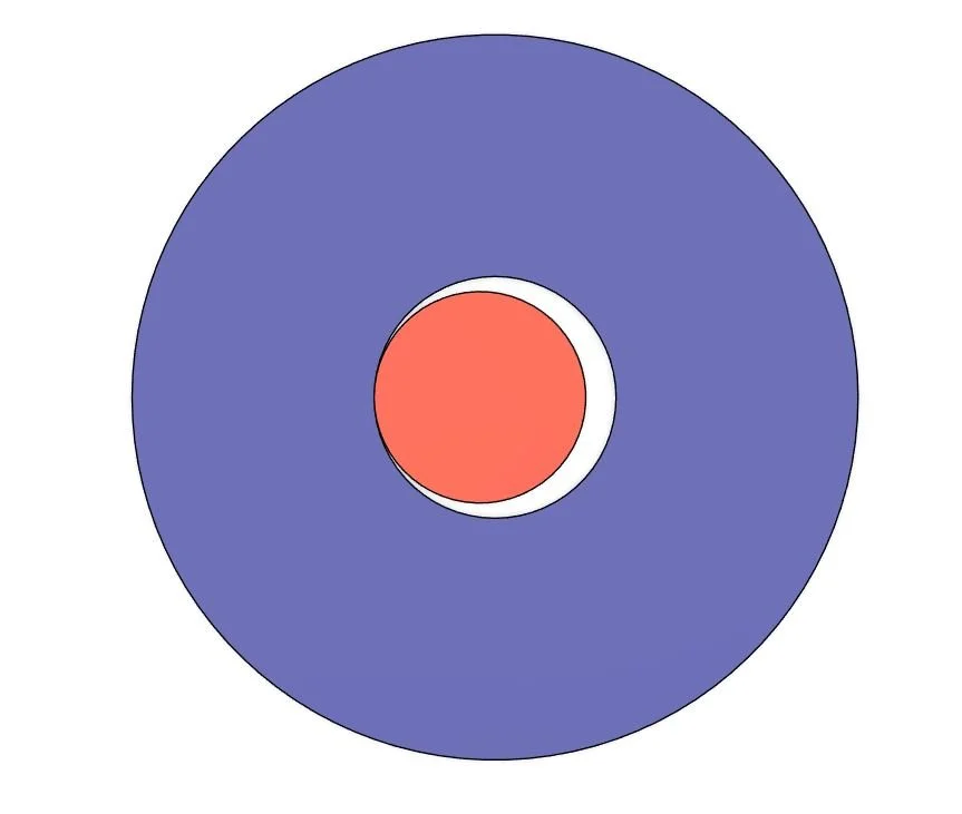
A visual representation of the issue with an oversized melt zone bore. Blue is hotend, red is filament.
With this in mind, it seems as though many of the high flow melt zone geometries (CHT, bozzle, tri-lobe, etc) on the market may have a hidden mechanism of improving flow that is unintentional. More or less, all of these geometries force the filament into contact with the melt zone walls early in the melt zone while allowing space for deformation to prevent the choke point issue of the smaller melt zone.
How does Vesuvius Lite work?
Vesuvius Lite’s secret? SLM…
More specifically, the surface texture that results from SLM 3D printing combined with a tight tolerance melt zone around the filament helps to initiate and maintain thermal contact early in the melt zone. In essence, what this accomplishes is a still round cross section with very small rough protrusions. These protrusions and bumps (which are a natural byproduct of SLM 3D printing) are able to dig into the side of the filament slightly and initiate thermal contact while providing enough resistance for the softened walls of the filament to balloon out and make full contact early in the melt zone. More or less, this surface texture forces the filament to fill out the melt zone almost immediately by gripping onto and slowing down the outside of the material as it transitions from solid to viscoelastic.
Our first big clue about this behavior is in testing data we have from early prototypes of VL, in particular the performance comparison between a machined heat block and an earlier SLM heat block. We initially prototyped VL with SLM as it was the easiest way for us to experiment with different concepts, however we were originally planning on transitioning to machined brass for the production models of the hotend. However, when we transitioned to brass we noticed a reduction in flow rate by about 25% (90mm^3 to 70mm^3). This baffled us, as all conventional logic states that the smooth brass should have less resistance. After diving back into CFD and experimenting with various other test articles, we concluded that the rough surface of the SLM part was the driving factor behind this improvement in flow rate.
We decided to try pushing this concept further as well. Since we own and operate our own SLM machine that is used for printing all of our components, we are able to control the laser focus and print parameters. This allowed us to experiment with a system where the main melt zone was printed at a setting that provided the smoothest possible surface finish, while the initial ~6mm of the melt zone were made to be very rough. This achieved even better results, pushing the flow rate with identical material and temperature up to 100mm^3/s+.
We are not the only ones to have noticed this about SLM 3D printed melt zones (or rough melt zones in general). Several other notable people that have pointed out some unexpected results from rough melt zone surfaces are Roetz 4.0 (on youtube and discord), Monika McWuff, and Strantor (on discord). In particular, some have also noticed that artificially roughening the beginning of a melt zone can also have a similar effect.